Lawn Mower 7 Terminal Key Switch Diagram : IGNITION SWITCH CUB CADET 725-3163 : Read 2001 dodge ram 2500 radio wiring diagram download.. With a cub cadet tractor or lawn. Hd switch starter ignition switch wire harness 7 terminal connector repair kit replaces john deere gy20074 am132807 am133597 and fits l la d lt x series, l120 l130, all sabre scotts models. If this part becomes broken it will need to be replaced and a screwdriver may be needed during the installation process. This part is made of metal and is sold individually. Lawn mower 7 terminal key switch diagram :
Remove the key from the ignition switch, engage parking brake, and pull the wire(s) off the. From 7 terminal ignition switch, 4 post solenoid or the popular briggs and stratton ignition switch 5 terminal all these key switches are used on riding mowers. If you can send a picture of the bottom of the switch there are numbers near each terminal that tell you a circuit. If this part becomes broken it will need to be replaced and a screwdriver may be needed during the installation process. R is typically to indicate red wire out to components that need 12v power in the run position of switch (cub to name one).
Indak Ignition Switch Wiring Diagram from i0.wp.com Craftsman riding lawn mower ignition switch wiring diagram all round hobby. We have accumulated lots of images. Hd switch starter ignition switch wire harness 7 terminal connector repair kit replaces john deere gy20074 am132807 am133597 and fits l la d lt x series, l120 l130, all sabre scotts models. 1.1 all components involved in these steps are:; I need a wiring diagram for a 7 terminal ignition switch on a huskee riding mower. Please refer to your subwoofers owners manual for the proper wiring of its terminals. Lawn mower 7 terminal key switch diagram. Check spelling or type a new query.
Buy a 7 terminal switch 5412k for your lawn equipment the 7 terminal ignition switch comes with two keys and helps to turn the vehicle on and off.
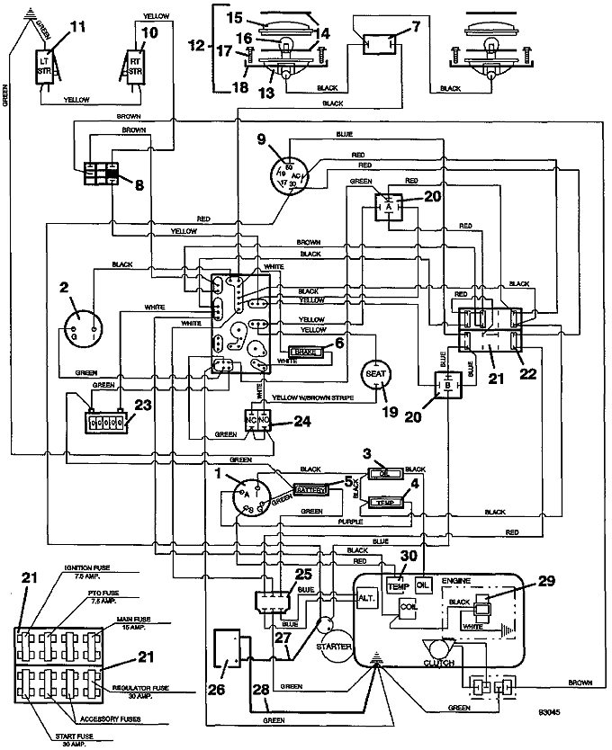
Of terminals 7 manufactured by delta systems inc. This key switch is off of a cra. Riding mower starting system wiring diagram part 1. This part is made of metal and is sold individually. Remove the key from the ignition switch, engage parking brake, and pull the wire(s) off the. With a cub cadet tractor or lawn. Briggs and stratton ignition switch sterling wiring diagram diagrams to help you understand tractor ford 535 mtd forum key farm tractors universal 4 pole craftsman riding mower terminal breakerless boat color code wire lawn ezr 1742 parts for dixon allischalmers 1710 2000 my poulan pro po17542sta repair pdf 2005 2011. When you employ your finger or stick to the circuit together with your eyes, it may be easy to mistrace the circuit. Www.metalinmotionshop.commetal in motion based in lenoir city tn, shows you the concept of testing a riding mower key switch. How to test a 5 prong lawnmower ignition switch. M = magneto s = starter solenoid l = lights a = accessory b = battery g = ground i = ignition r = regulator/rectifier the designated terminal connects in some manner to that component. M = magneto s = starter solenoid l = lights a = accessory b = battery g = ground i = ignition r = regulator/rectifier the designated terminal connects in some manner to that component. Connect the switch to ground;
Remove the key from the ignition switch, engage parking brake, and pull the wire(s) off the. With that said, let's look at murray riding lawn mower craftsman switch, as the majority of your lower end mowers will carry this type of key switch. We did not find results for: Please refer to your subwoofers owners manual for the proper wiring of its terminals. The 7 terminal ignition switch comes with two keys and helps to turn the vehicle on and off.
Top 6 Ignition Switch for Craftsman Riding Lawn Mower ... from nobsoc.com B is for the input from the battery source'. With a cub cadet tractor or lawn. Complete exploded views of all the major manufacturers. Riding mower starting system wiring diagram part 1. If you have a large garden or lawn at your residence, a cub cadet tractor is a wonderful piece of equipment for common maintenance jobs. Largest range of products on offer in australia. M = magneto s = starter solenoid l = lights a = accessory b = battery g = ground i = ignition r = regulator/rectifier the designated terminal connects in some manner to that component. If you can send a picture of the bottom of the switch there are numbers near each terminal that tell you a circuit.
R is typically to indicate red wire out to components that need 12v power in the run position of switch (cub to name one).
Lawn mower 7 terminal key switch diagram / murray electrical parts. Largest range of products on offer in australia. Lawn mower 7 terminal key switch diagram : Of terminals 7 manufactured by delta systems inc. L can indicate lights if lights function is part of the key switch duties (may have other functions on different machines. If you have a large garden or lawn at your residence, a cub cadet tractor is a wonderful piece of equipment for common maintenance jobs. Craftsman riding lawn mower ignition switch wiring diagram from i0.wp.com. Find solutions to your ignition switch diagram riding mower question. Check spelling or type a new query. From 7 terminal ignition switch, 4 post solenoid or the popular briggs and stratton ignition switch 5 terminal all these key switches are used on riding mowers. Bob testing an ignition switch is pretty simple, there will be one power input and the other terminals will all get power at different points of the ignition being turned. Ignition key switch fits john deere la165 la175 s240 x110. The letters on the back of an ignition switch stand for the following:
Of terminals 7 manufactured by delta systems inc. This key switch is off of a cra. John deere lawn mower wiring diagram image. Find solutions to your ignition switch diagram riding mower question. For example, the b terminal connects in some manner to the positive battery cable.
Model 721 1994 Wiring Assembly - Grasshopper Lawn Mower ... from www.the-mower-shop-inc.com Craftsman riding lawn mower ignition switch wiring diagram from i0.wp.com. Lawn mower 7 terminal key switch diagram / murray electrical parts. M = magneto s = starter solenoid l = lights a = accessory b = battery g = ground i = ignition r = regulator/rectifier the designated terminal connects in some manner to that component. If you can send a picture of the bottom of the switch there are numbers near each terminal that tell you a circuit. We also have installation guides, diagrams and manuals to help you along the way! Operating a lawn mower doesn't have to be a complicated process, but it can be a little daunting for first timers or those switching to a new type of mower. Not only will it assist you to achieve your desired outcomes more quickly, but also make the complete method. Briggs and stratton ignition switch sterling wiring diagram diagrams to help you understand tractor ford 535 mtd forum key farm tractors universal 4 pole craftsman riding mower terminal breakerless boat color code wire lawn ezr 1742 parts for dixon allischalmers 1710 2000 my poulan pro po17542sta repair pdf 2005 2011.
Operating a lawn mower doesn't have to be a complicated process, but it can be a little daunting for first timers or those switching to a new type of mower.
Read 2001 dodge ram 2500 radio wiring diagram download. Lawn mower 7 terminal key switch diagram : Lawn mower 7 terminal key switch diagram. Please refer to your subwoofers owners manual for the proper wiring of its terminals. With a cub cadet tractor or lawn. L can indicate lights if lights function is part of the key switch duties (may have other functions on different machines. B is for the input from the battery source'. Complete exploded views of all the major manufacturers. Riding mower starting system wiring diagram part 1. We did not find results for: With such an illustrative guidebook, you will be able to troubleshoot, stop, and total your projects with ease. The marking on wiring schematic should line up to markings on original switch.indak 6 prong ignition switch wiring diagram is among the most images we found on. Maybe you would like to learn more about one of these?